Computer Vision Deepfake ID Detection

Computer Vision Deepfake ID Detection For a Dutch Digital Bank

How adding a custom computer vision layer to the existing SaaS ID verification platform empowered a Dutch digital bank to keep up with the evolving threat landscape and stop 30% more AI-generated identity fraud, while reducing false positives for real users by 60% and decreasing manual document review workload by 40%.

Business challenge

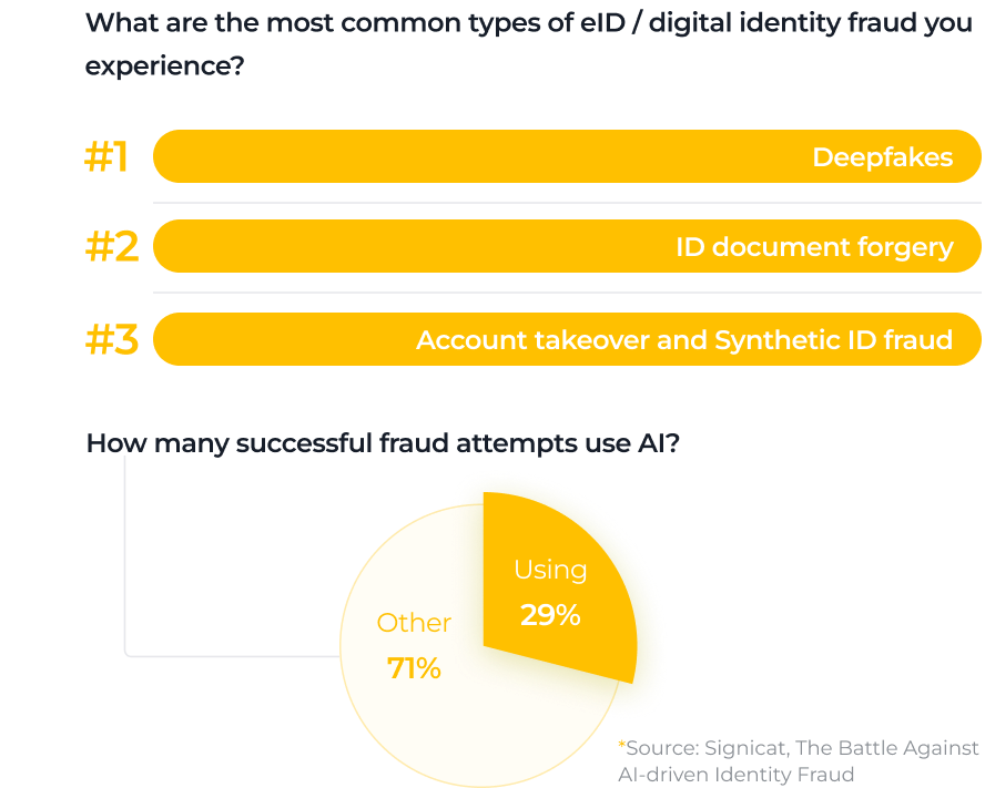
Bar chart listing common types of digital identity fraud: 1. Deepfakes, 2. ID document forgery, 3. Account takeover & synthetic ID fraud. Pie chart: 29% of successful fraud uses AI, 71% uses other methods. Source: Syntiant.
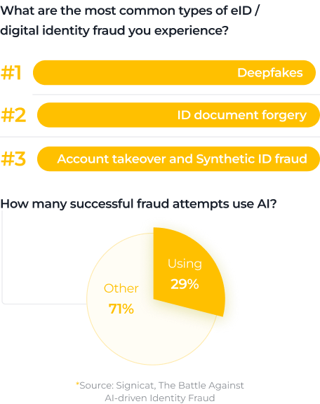
A graphic showing the top three eID/digital identity fraud types: #1 Deepfakes, #2 ID document forgery, #3 Account takeover and synthetic ID fraud. A pie chart shows 29% of successful fraud uses AI, while 71% is categorized as “Other.”.
A graphic lists the top three eID/digital identity fraud types: #1 Deepfakes, #2 ID document forgery, #3 Account takeover and Synthetic ID fraud. A pie chart shows 29% of successful fraud attempts use AI, while 71% are other types. Source: Signicat.

When GenAI emerged as a viable tech capability, businesses weren’t the only ones who went for it. So did cybercriminals who used the technology to create highly realistic deepfakes and pass Know Your Customer (KYC) onboarding at digital banks. Since the mass adoption of artificial intelligence, the number of AI-generated identity fraud cases in fintech has increased by 2137%. Now, 1 in 15 attacks involves deepfakes, and 29% of them succeed.

Our client, a Netherlands-based digital bank serving customers across the European Economic Area, chose to be one step ahead of fraudsters. As the bank onboards 4-5 million new users annually, they must protect real customers from account takeover, not to mention safeguarding brand trust in a highly competitive digital banking market.

At the time, the client relied on a third-party SaaS identity verification (IDV) platform with OCR and NFC/RFID technologies at its core, which fell short on several fronts:

  1. Failures in detecting AI-generated identity documents. Passports with AI-altered images or completely fake documents could pass through the checks if they visually match the templates of authentic IDs.
  2. Slow speed of adaptation to fraud patterns. The SaaS IDV was tied to the vendor’s release cycles, meaning weeks of waiting for new reported fraud cases to be updated in the system’s detection logic, while the new attack patterns kept snowballing.
  3. Limited control over the deepfake detection mechanism. The client’s team didn’t have direct access to the underlying algorithm and couldn’t strengthen the SaaS IDV’s forgery detection and analysis by training it on their own fraud samples.

For a bank operating at a multi-million-user scale, the gap between their needs and software capabilities posed significant financial and reputational risk. They needed a tech partner with proven expertise in finance to address the issue.

Solution

Instinctools’ dedicated team looked into ways to strengthen the client’s identity verification algorithm. Investing in a custom computer vision-based deepfake detection to run alongside the SaaS IDV proved to be the most beneficial option, as it enabled hotfixes and retraining on confirmed internal fraud cases within days.

Our computer vision experts took full ownership of the system’s design, training, calibration, and production rollout.

  1. Assembling a fraud-realistic dataset

The effectiveness of the custom CV detection mechanism hinged on the quality of the training data. Generic examples of ID fraud, that the off-the-shelf IDV platform had covered, were not enough. Therefore, our team prioritized assembling a solid dataset.

  • Doubling down on data preparation (exploration, cross-source collection, cleanup) to reduce training time.
  • Defining attack taxonomy that reflected the most relevant fraud patterns, from partial manipulations of photos, textual and numerical data to fully AI-generated documents.
  • Building a dataset that included the fake IDs the staff caught during KYC checks, partly and completely synthetic documents, and legitimate but low-quality photos and scans of passports.
  • Increasing the share of hard negatives in the dataset through data augmentation. Valid documents with blur, glare, or perspective distortion often triggered false alarms in the SaaS IDV platform, and we wanted to avoid this issue by training the custom CV algorithm to accurately distinguish poor capture quality from actual manipulation.
  • Labeling the data based on different criteria (real document vs. fake, fraud location, etc.).
  1. Designing an ID-focused CV pipeline

What is YOLO?

YOLO (You Only Look Once) is a computer vision object detection model. It’s an example of a leading-edge single-stage detector, known for its ability to locate and classify objects in a single pass through the network and, therefore, a go-to option for real-time object detection.

Our team built the solution around a single, well-controlled YOLO-based computer vision pipeline, tailored for identity document analysis. The model excels at:

  • Detecting the presence of a document
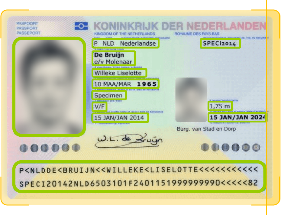
  • Localizing and analyzing in a single pass critical document regions, such as the data page, portrait area, and MRZ code
  • Highlighting suspicious area(s) of the document
  • Providing a risk score for each problematic element to simplify and speed up the review process

This approach ensured consistency while keeping inference fast enough for real-time KYC flows.
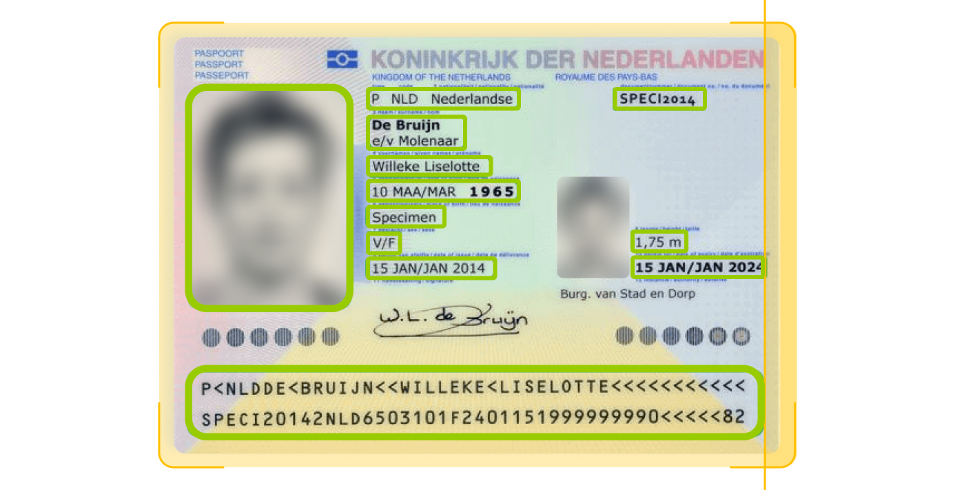
A sample Dutch passport shows personal details: a blurred photo, name “WiIieke Liselotte De Bruijn,” date of birth 10 March 1965, height 1.75m, and expiry date 15 January 2024. Text is in Dutch and English with blue and orange highlights.
A Dutch passport for Willeke Liselotte de Bruijn with personal details, passport photo, and security features. The passport text is in Dutch and English, and highlighted sections include name, birth date, height, gender, and document number.
  1. Ensuring the detection is reliable beyond known fraud patterns

To avoid building a system that works only for already known fraud tricks, we focused on how well the solution would hold up when attackers change their techniques and tools. Therefore, we deliberately checked it against document manipulations and generation methods it hadn’t seen before.

The test dataset included:

  • Data created by the same top 10 deepfake generation tools we used when assembling the training dataset, but with different faces and parameters
  • Data generated by other tools that weren’t used for creating the training dataset

This approach ensured the detection logic wasn’t tied to a specific deepfake tool or editing technique, but rather to the visual inconsistencies that tend to appear across AI-generated and manipulated documents, so the custom CV system remains effective even if fraudsters switch to new image generators.

  1. Decision threshold calibration

One of the key challenges with the SaaS IDV platform was the sensitivity of its fraud calibrator, which sometimes caused it to reject legitimate customers due to minor issues (like glare in a photo) while overlooking more serious fraud attempts. To address this problem, we linked the decision thresholds to the risk scores.

The custom CV layer now follows a tiered decision logic:

  • Low-risk cases continue through onboarding automatically, without any additional steps
  • Middle-risk cases trigger targeted step-ups, such as an NFC scan, requesting  an extra selfie or a short video
  • High-risk cases are flagged for manual review or outright rejection

This approach helped the client strengthen fraud controls and decrease the workload of human reviewers while ensuring fast onboarding for legitimate users.

  1. Seamless integration
of the CV layer into the client’s KYC flow

To keep the onboarding experience unchanged for customers, we deployed the custom computer vision system as a decision microservice within the existing onboarding pipeline. 

Still, before letting it influence real onboarding decisions, the team ran the custom CV system in observation mode. At this stage, it processed live KYC traffic alongside the existing systems, but its outputs were not used to approve or reject customers. 

Once we validated that the model behaved as expected with real-world data, we rolled it out gradually by feeding it controlled portions of traffic, expanding coverage step by step. This phased approach ensured that the new detection layer strengthened fraud controls without unintended consequences, such as over-flagging legitimate users or missing edge cases.

Here’s how the client’s updated KYC flow works:

  1. A user submits their documents (and, if required, a selfie or short video)
  2. The existing SaaS IDV platform performs its standard checks, such as OCR, MRZ reading, and NFC validation
  3. The custom computer vision system analyzes the same inputs in parallel
  4. The higher-level KYC orchestrator then collects and combines the results from both systems and applies the bank’s decision logic to determine the next action (approval, step-up verification, or manual review)

Since all checks run behind the scenes and in parallel, customer experience stays the same, with no extra waiting time or redundant requests. Meanwhile, under the hood, confirmed fraud cases are auto-labeled and folded into retraining cycles within days, enabling hotfixes. As a result, deepfake document detection had shifted from a static vendor capability to a living, bank-owned system evolving at the same pace as the threat landscape.

Before

  • Deepfake document detection depends entirely on a third-party SaaS IDV platform
  • AI-generated or partially manipulated documents highly resembling valid ID templates the SaaS platform was trained on could pass checks, while low-quality documents from real customers could have been rejected as synthetic
  • Time-intensive manual reviews due to the software’s unreliability
  • Weeks-long response to new deepfake techniques due to vendor-controlled update cycles

After

  • Custom, bank-owned computer vision layer added on top of the existing SaaS IDV platform
  • The CV system is trained on a high-quality dataset and follows tiered decision logic to perfect deepfake detection without affecting legitimate customers
  • Reduced review workload on the humans in the loop thanks to the well-calibrated decision logic
  • Adaptation to new deepfake patterns within days thanks to hotfixes

Business value

  • + 30% in detected synthetic document fraud
  • – 60% falsely flagged legitimate users
  • – 40% in manual review workload

Client’s testimonial

Multiplier effect

Computer vision threat detection use cases extend far beyond digital banking. Any company that relies on document checks or user verification, from insurance and healthcare to travel and ecommerce, faces the same growing risk from AI-generated identities and forged documents. A custom computer vision system trained on real-world fraud patterns can help businesses react faster than when relying on generic vendor tools.

A person in a dark blue shirt holds a smartphone in one hand and types on a laptop with the other. Digital facial recognition icons and a checkmark appear, indicating successful facial authentication on the phone. The background is blurred.

Computer Vision Defect Detection

Computer Vision Defect Detection For an Electronics Manufacturer

How switching from a rule-based machine vision system to an advanced computer vision solution for early-stage defect detection on the production line helped an electronics manufacturer reach 97,4% accuracy in identifying flaws and save $2.4 million annually thanks to a drop in warranty claims.
Business challenge

Our client is a Saudi-based electronics manufacturer producing laptops for the MEA region in partnership with one of the global tech leaders. Years earlier, we had created digital twins of their factories, so when new challenges surfaced, the client turned to us again. 
The company had long moved from fully manual defect detection on the production line to an automated, non-contact product quality inspection. However, their automated optical inspection (AOI) in the conveyor video surveillance system was too demanding, rigid, and costly, posing numerous limitations. 

  • Overdependence on consistent imaging. The system cannot function efficiently if lighting and camera positioning aren’t stable.
  • Inflexibility. AOI operated on strict “if-else” rules, making the system unable to perform continuous trend analysis and adjust dynamically to enhance both speed and accuracy of defect detection. 
  • Slow adaptability. Every time the component configuration, size, or color changed, the system required recalibration. 
  • Low scalability. One AOI system couldn’t simply be replicated across multiple factories. Each production line will require extensive manual parameter tuning. 
  • Costly maintenance. Traditional machine vision systems like AOI require highly specialized experts to take over routine manual inspections, regular calibrations, software updates, and hardware repairs. 

The client needed a more flexible, scalable, and budget-wise form of computer vision at the core of their conveyor video surveillance system.

Solution

Our development team ensured the smooth shift from basic AOI to advanced computer vision.

  1. Shaping up the tech stack

We decided to rely on a pre-trained object detection and image classification model. Then, we had to choose between single- and two-stage detectors to perform object detection. The scale was tipped in favor of a single-stage algorithm due to its several advantages:

  • Faster inference
  • Lower computational demand
  • Easier maintenance

Having experience with various single-stage detectors, we settled on YOLO over CenterNet, SSD, RetinaNet, and FCOS, as it offers superior inference speed, ensuring truly real-time performance. Despite YOLOv10 being available, we used YOLOv8, as it was the most tested and stable version at the moment.

  1. Optimizing the training dataset

The client’s previous pre-computer vision system relied on a three-tier defect classification framework: “definitely defective,” “borderline,” and “definitely non-defective”. Rather than discarding the existing dataset, we capitalized on it by strengthening defect coverage and enforcing consistent, high-quality labeling.

Augmenting data to address the class imbalance issue

The original dataset was limited in size, with a maximum of 200 images per defect category. In addition, different defect types weren’t represented equally. For example, issues such as missing components and incorrect placement appeared far more frequently than subtler issues like misalignment, solder defects, open circuits, or lifted leads.

To address both the small dataset size and class imbalance, we applied data augmentation techniques:

  • Random photo cropping and flipping
  • Controlled blurring and noise injection
  • Tweaking lighting
  • Changing the background

That way, we multiplied the dataset tenfold while ensuring balanced representation across all defect categories.

Improving labeling consistency and reliability

Given the diversity of subtle defects, high-quality labeling was a must-have. Our AI engineers focused on refining the labeling process to: 

  • Reduce annotation noise
  • Improve consistency across classes
  • Enable more statistically reliable quality assessments

In addition, we ensured the dataset included images both with and without the target object, improving the model’s ability to distinguish true defects from background artifacts and, thus, reducing the false positive rate.

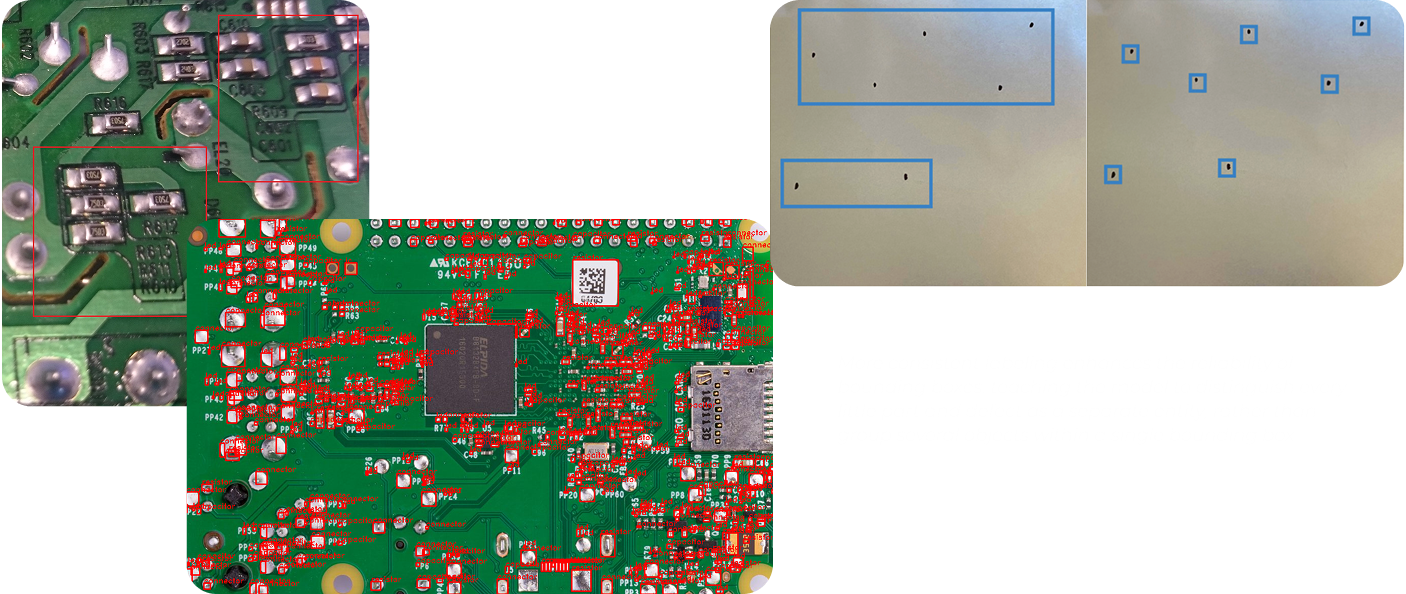
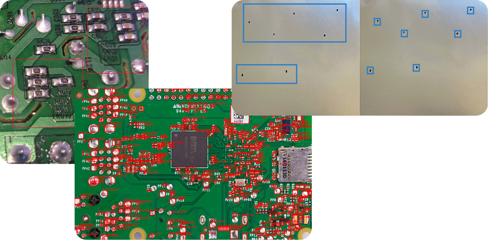
A collage showing two close-up images of green circuit boards with various electronic components and solder points, and one image of a metallic surface with blue rectangular and square outlines marking different areas. Text is faintly visible in the bottom right corner.
Three images: a close-up of a green circuit board showing silver solder joints; a larger green circuit board with many red and silver components and a central microchip; and a metallic panel with blue-outlined rectangular and square cutouts.

More consistent labeling enhances the reliability of bounding boxes, teaching the model to distinguish every little part and defect as a separate entity, rather than group several objects within a single bounding box.

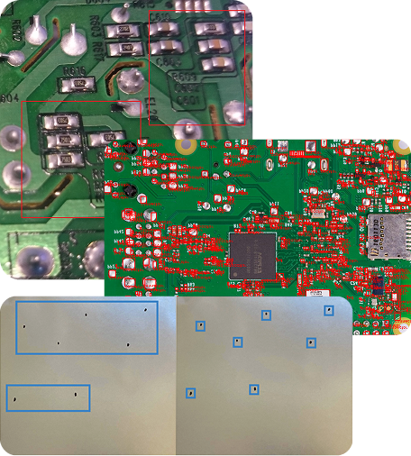
A collage of three images shows close-ups of green circuit boards with red components and microchips, overlaid with a photo of a metal plate featuring multiple cutouts and small square and rectangular holes highlighted in blue.

More consistent labeling enhances the reliability of bounding boxes, teaching the model to distinguish every little part and defect as a separate entity, rather than group several objects within a single bounding box.

  1. Running model transfer learning on the enhanced dataset

Models for object detection and classification like YOLO are already trained on hundreds of millions of general images. However, to accurately address the client’s specific needs, it had to undergo additional training on the updated dataset.

Instinctools’ AI engineers took an efficient approach to tackle this challenge. They resorted to transfer learning as an ML training technique to improve the model’s performance:

  1. Started with a pretrained YOLO model
  2. Used PyTorch to remove the default classifier head
  3. Replaced the model’s classifier head with the enhanced dataset

After that, YOLO was able to instantly detect and classify all the specific defects relevant to the client’s production line.

What is transfer learning in computer vision?
 
Transfer learning is a machine learning training technique, which capitalizes on the pre-trained model’s general knowledge (the ability to detect different defects on various surfaces) instead of training the model from scratch.
 
With transfer learning, you only retrain the model on your task-specific dataset (examples of external and internal defects of the client’s laptops), enabling the model to adapt its existing knowledge to your reality. This method significantly reduces training time and computational resource consumption.
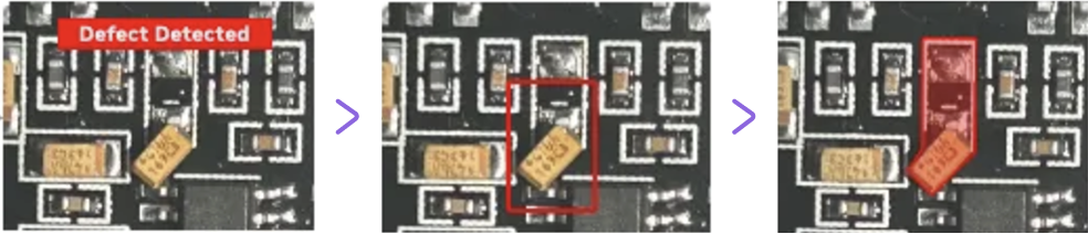
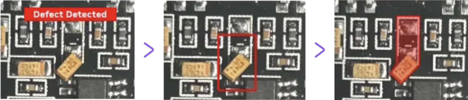
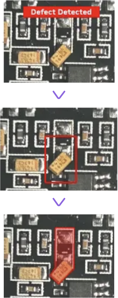
Three images show a circuit board section. The first has a red “Defect Detected” label, the second outlines a component in red, and the third highlights the component with a red overlay, indicating the defect’s location. Purple arrows separate each step.
Three stacked images of a circuit board: 1. Top image highlights a component with a red “Defect Detected” banner above. 2. Middle image shows the same area outlined with a red box. 3. Bottom image shades the component in red, marking it as defective.
  1. Calibrating defect inspection thresholds 

Defining a defect is only part of the process. Next, our dedicated team helped minimize the number of items wrongly discarded at the production stage through:

  • Raising a confidence threshold ratio from 0.5 to 0.85 to prevent the model from flagging low-certainty cases as sure defects 
  • Setting up detailed defect severity scoring to minimize false positives while not letting critical defects slip further
  • Adjusting NMS (Non-Maximum Suppression) parameters so that the model always chooses one clean, highest-confidence box per object instead of overlapping bounding boxes
  1. Going the extra mile for near-100% defect detection accuracy 

After transfer learning and threshold calibration, the model’s accuracy reached 86,5% which was already more than 15% higher than with the previous AOI system. Still, our team aimed for as close to 100% accuracy as possible.

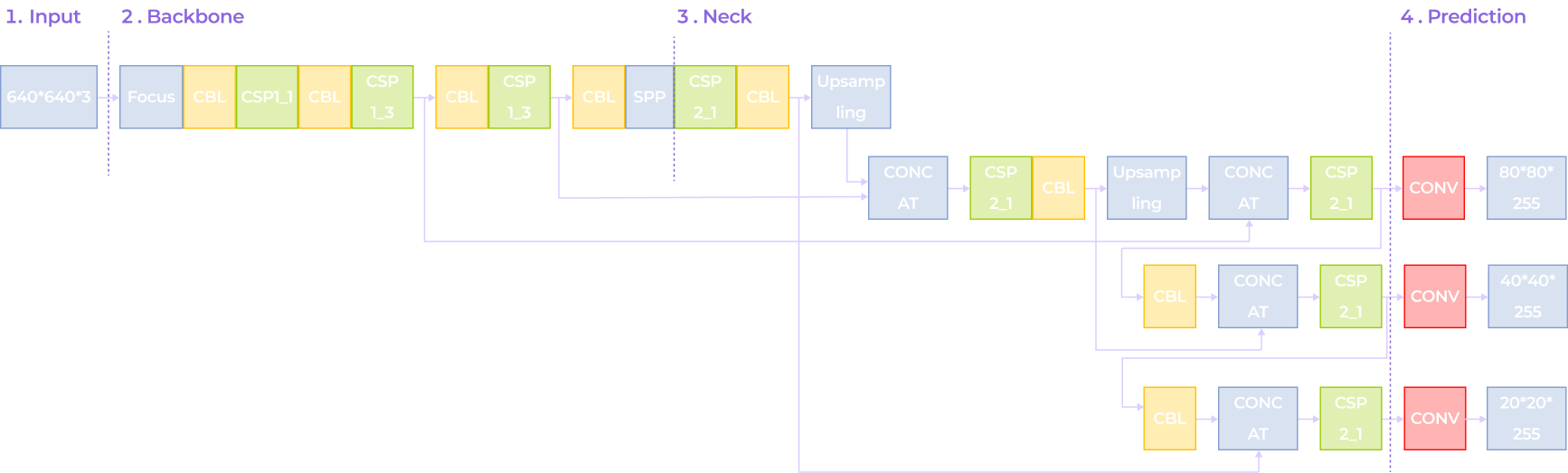
Instinctools’ AI experts enhanced YOLO-based defect detection capabilities by applying:

A flowchart showing a neural network architecture with four stages: Input (640x640x3), Backbone, Neck, and Prediction. Colored blocks represent layers like Focus, CBL, CSP, SPP, and CONV, with branching paths for multi-scale predictions.
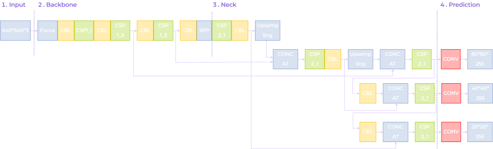
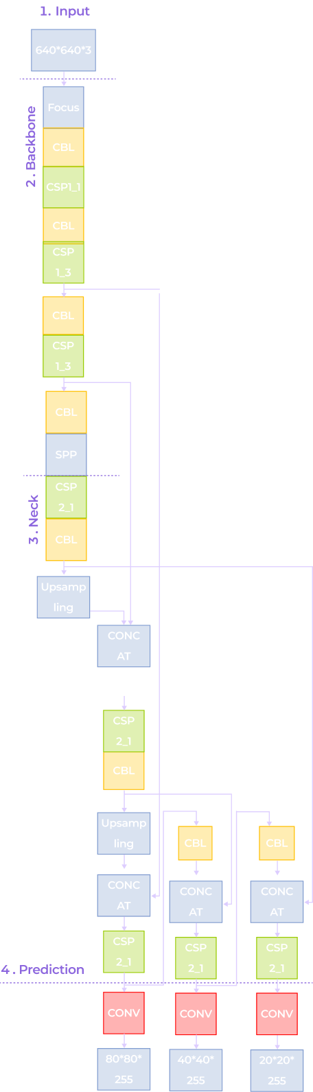
A flowchart of a neural network architecture with four sections: Input (640x640/3), Backbone (Focus, CBL, CSP, SPP), Neck (CSP, Upsampling), and Prediction (Conv layers with outputs: 80*80/255, 40*40/255, 20*20/255).
A vertical neural network diagram with four labeled sections: Input (640×640×3), Backbone (Focus, Conv, CSP1, SPP), Neck (Upsampling, Concat, CSP2), and Prediction (Conv layers with outputs: 80×80×255, 40×40×255, 20×20×255).
  • Depthwise Separable Convolution (DSConv) to accelerate the model’s inference speed
  • The Cross-Stage Partial Network (C3 module) to combine low-level detailed information with high-level semantic data, enhancing the model’s adaptability to target scale variations and improving detection accuracy
  • The Bidirectional Feature Pyramid Network (BiFPN) to enable the model to identify fine features of small targets, improving its recognition capability
  • The DySample upsampling operator to minimize detail loss and boost accuracy for small targets

With these enhancements, the new CV defect detection system consistently hits the 97,4% accuracy benchmark.

  1. Integrating the CV mechanism into the client’s manufacturing execution systems (MES)

The computer vision solution was installed at one of the client’s facilities. There, it underwent further model training based on collected metadata and outputs generated by the system during operation. Those adjustments helped align the system with real-world production conditions and replaced AOI at each critical juncture:

  • Post-solder paste application. The system verifies if paste volumes are adequate and properly aligned.
  • Post-component placement. The solution validates whether each component is present, oriented correctly, and positioned within acceptable tolerances.
  • Post-reflow. Software runs a final check for defects such as tombstoning, bridging, and cold solder joints.
The result is an all-encompassing, multi-class defect classification, with all defects categorized by type and severity.
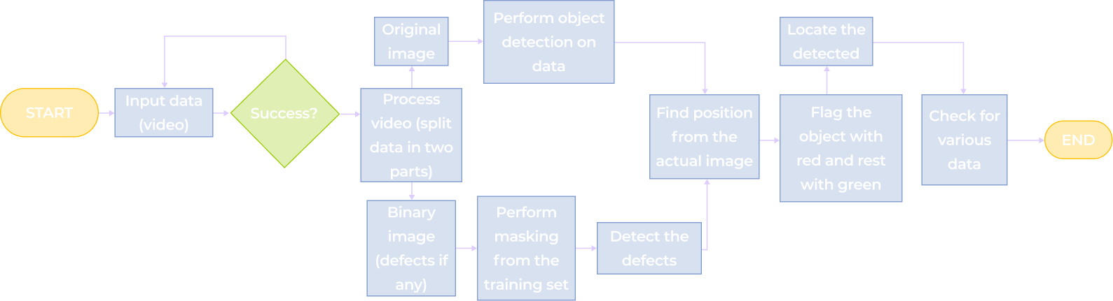
A flowchart for video object detection: Starts with Input data (video), checks Success?, then branches to process the image or video, detects defects, locates them, flags with red and green, checks for various actions, and ends the process.
A flowchart for object detection in video: start with video input, check for success; if yes, process original image and video; create binary image, mask defects, then perform object detection, locate defects, flag objects, and check results to end.
A vertical flowchart shows steps from inputting video data, processing and splitting the video, detecting objects and defects, flagging objects, checking data, and ending. Steps are in colored rectangles with directional arrows connecting them.

As the solution features cloud connectivity, our team can remotely perform model updates, configuration changes, and CV algorithm optimizations. 

Before

  • A rigid and costly machine vision system that has to be configured for each production line
  • Real-time defect detection is only possible under perfectly stable lighting 
  • 70% accuracy of defect detection
  • Items falsely discarded as defective

After

  • Flexible and highly scalable computer vision system that can be reused across production lines
  • Real-time defect detecting under any lighting conditions
  • 97,4% accuracy of defect detection
  • < 0,5% discarded items

Business value

Operational impact:
  • + 27,4% accuracy of production line inspections 
  • + 24% in production throughput due to immediate defect detection
  • < 2% false positive rate
  • < 0,5% discarded items 
  • – 67% defect-related warranty claims
Financial impact:
  • – $1.2 million in waste-related costs
  • + $2.4 million annually due to the drop in warranty claims 
  • – 26% in quality control labor costs

Client’s testimonial

Multiplier effect

Stronger quality-control systems on a production line lead to fewer defective products reaching customers and ruining their experience. With the stakes as high as one in three customers* leaving a brand after a single bad experience involving defective products, playing it safe becomes essential for business survival.

Computer vision can be the key to achieving higher-quality products and improved customer satisfaction. 

*According to PwC

A diverse group of six people sit around a table with papers, coffee, and devices, engaged in discussion. Overlaid text reads Customer Feedback: Connect with your friends. Notification icons and messages appear around the image.

Web App For Robotics Manufacturer

Intuitive Web App For Robotics Manufacturer

How crafting a web app with an easy-to-grasp interface and flexible architecture empowered a manufacturer of warehouse driverless forklift systems to unlock new value-creation opportunities and reach SMB customers.

Industry:
Logistics, Manufacturing

Enterprise Automation

UX and Design

Web Development

MVP Development

Software Product Development

Business challenge

Under-automated or under-digitized intralogistics inevitably affects a company’s profits. However, sometimes the bottlenecks aren’t that obvious, and even organizations with warehouse-specific software and robotics in place struggle to achieve the much-coveted outcomes of intelligent automation.

The issue may lie in having overcomplicated software designed for tech-savvy users that holds down the company’s capabilities in efficient control and optimization of the goods flow within a manufacturing facility, warehouse, or distribution center.

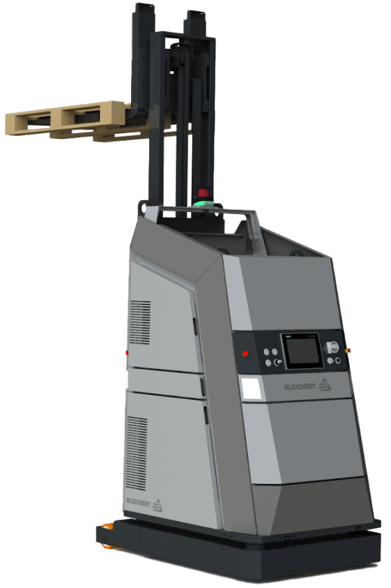
For example, navigating the driverless forklift systems in small spaces is quite a challenge, as such robots are usually designed for large warehouses. The equipment can neither go near fire exits nor stop near them by default. However, following these settings is tricky in small spaces with little room for maneuvering. Hence, when the robot has no other way than to make a path near the fire exit, it stops before reaching it. Such cases require manual human input to restart the system with an updated route.

Our client, Bleichert, an automation machinery manufacturer, wanted to address two pain points of their customers seeking warehouse robotics:

‘By engineers, for engineers’ approach in designing the software

Lack of targeted solutions for small and midsize businesses (SMB) in the market overloaded with enterprise-grade products

To reach SMB customers and provide them with user-friendly software for warehouse robotics, they decided to broaden their offering with an innovative model of their driverless forklift systems that move loads autonomously by following a pre-configured circuit. Bleichert partnered with NODE Robotics and integrated their software modules into the experimental forklift. However, they needed a reliable tech ally to create a web app with an easy-to-grasp interface for warehouse operators and managers.

Instinctools, with its comprehensive expertise shored up by a set of ISO certifications, filled the bill perfectly. Our dedicated team created an MVP with interactive features for the demo presentation at LogiMat – the International trade show for intralogistics solutions – in just seven weeks.

Solution

When reaching out to *instinctools, the client specified their requirements for the future application.

Architecturally significant requirements (ASRs) included:

  • Accessibility via common browsers, such as Google Chrome, Safari, Microsoft Edge, etc. with an identical look and feel
  • Flexible architecture to support and manage multiple robots in the future
  • Real-time updates of a robot mission

Non-functional requirements (NFRs) encompassed:

  • Quick and easy navigation with the rule of thumb “max three levels to reach the goal”
  • Less than 0.4 sec response to the user input
  • Color-coded interface to simplify operators’ work and avoid any possible costly mistakes

Detailed documentation empowered us to jump into development right away. Our software architects started with establishing a robust tech stack.

  1. Deciding on a tech stack

We zeroed in on the client’s requirements to shape an easy-to-maintain tech stack for the web app development.

  • Seamless compatibility with NODE OS. Bleichert already installed the autonomy OS for mobile robots on the experimental forklift system to handle map management and interact with the robot’s systems and sensors. Since the operational system with related plugins uses Python, we suggested sticking to this programming language and FastAPI framework for server development for the sake of tech stack consistency.
  • Fast user interface response times. Besides ensuring the mandatory ease of use for the warehouse operators, we had to take care of the app’s interface speed. Our frontend developers suggested going with a single-page application (SPA) using React JS for user interface development, as the framework’s component-based architecture and virtual DOM allow crafting UI with lightning-fast render times. By leveraging React JS development services, we ensured optimal performance and a seamless user experience.

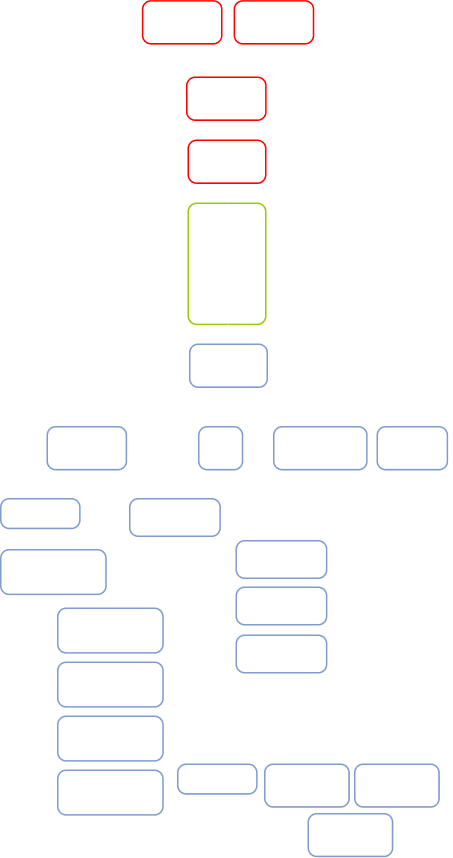
Here’s the high-level scheme of the future web app.

  1. Taking into account long-term usage scenarios from the onset

The MVP was tailored to user interaction with one robot (Master Robot) within a pre-configured environment. However, outlining the long-term project vision at the early stages is a best practice our team follows to eliminate head-scratchers in the future and enable a hitch-free development process.

Therefore, in our conversations with the client, we discussed two strategies their customers can choose from in the future when the app will operate multiple robots (Master Robots and Servant Robots).

  • Seamless compatibility with NODE OS

Such an approach provides end users with a single point of control for all forklift systems within the warehouse. However, the main drawback of this method is its high dependence on the Master robot. In case of its malfunctions, Servant robots won’t be able to perform their tasks.

  • The app runs on each of the Servant robots with one Master robot for covering managing tasks

In this case, Servant robots are highly independent, eliminating the risk of a work stoppage due to the issues with the Master robot, but high-level management becomes trickier.

The bone of the architecture at the heart of the web app is its flexibility. It can be tailored to either of these two options, depending on the client’s customers’ feedback on the innovative forklift model.

  1. Engineering and designing a user-friendly web app

Moving forward according to our Delivery Framework, we proceeded with iterative development, covering user roles, robot management, and more.

User roles within the app

The system has authorization and authentication mechanisms, but they aren’t mandatory, and non-authorized users can access the web app. Thus, we provided two modes within the system:

  • Basic user, designed for the rank-and-file warehouse operators with no authorization required
  • Key user, accessible only by authorized employees, for high-level warehouse operators and managers

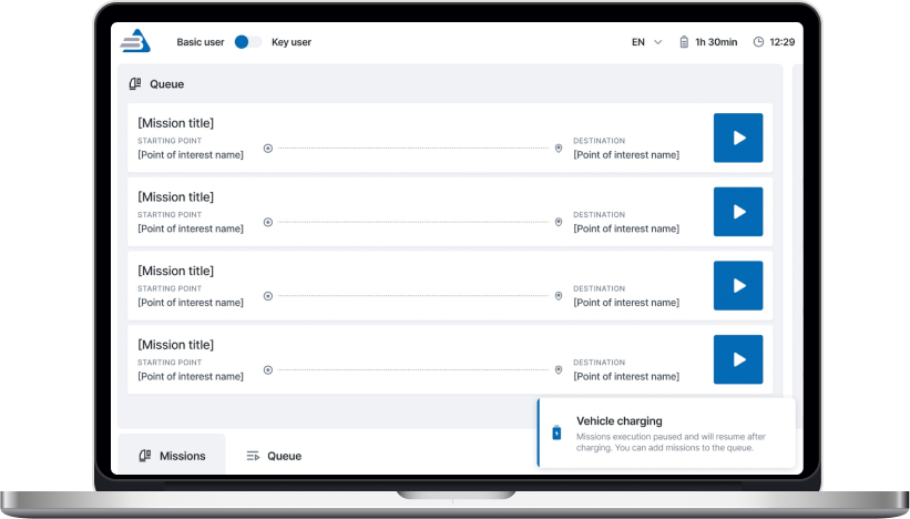
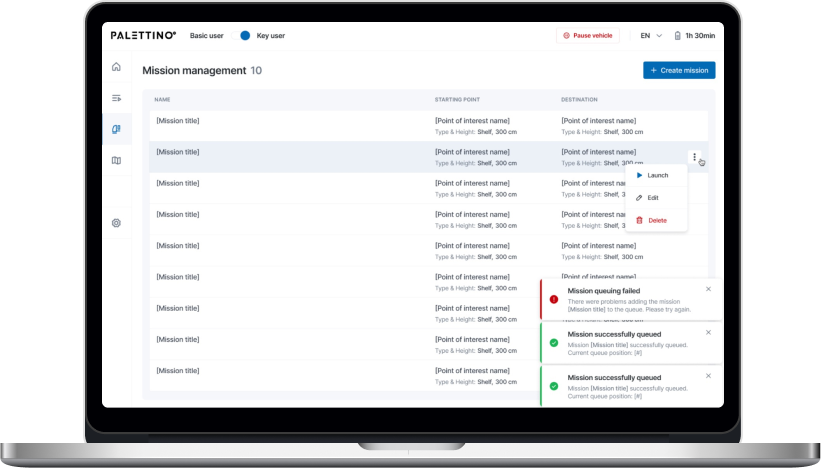
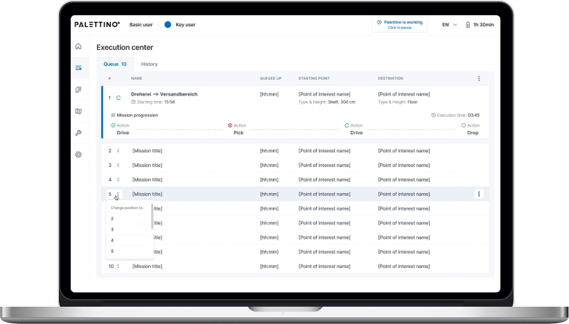
However, the capabilities of authorized and unauthorized users greatly vary. As you can see on a high-level app vision, Basic users can only view the list of existing robot missions and launch them, while Key users are allowed to create new routes and missions, add restrictions, view the history, check the robot’s status, etc.

Now, let’s dive deeper into the robot-related features.

Robot mission management

Each mission has the following attributes:

  • Name
  • Starting point of interest (POI)
  • Destination POI

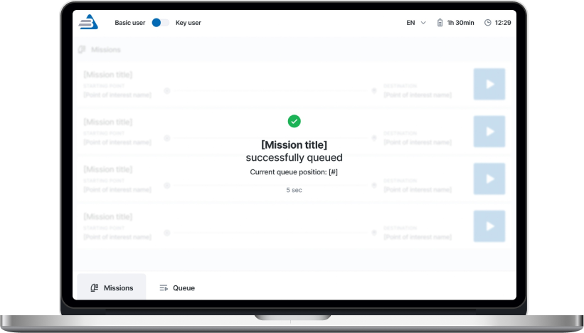
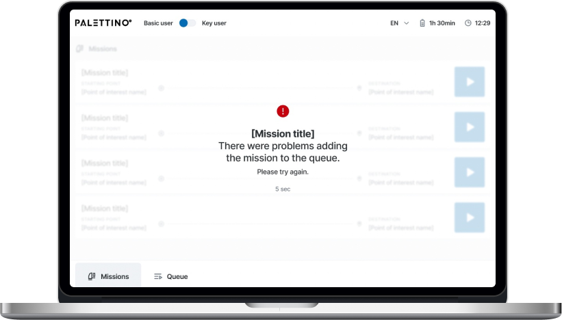
A Key user can add any mission from the list to the queue by clicking the “Play” button. The mission will appear at the last position after a five-second pause, during which the list of missions is locked. Then, the operator will be notified whether queuing the mission was successful or failed.

There are four mission statuses:

  • Active
  • Queued
  • Completed
  • Deleted

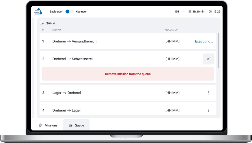
A Key user can remove any missions in the queue except the active ones.

Both Basic and Key users get toast notifications about events related to the robot’s operation. The alert about the robot charging is shown until the process is completed.

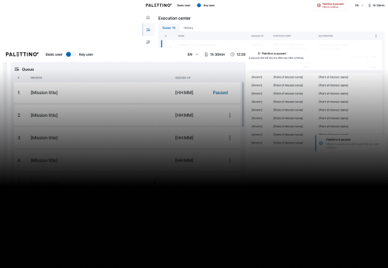
The opportunity to pause the robot is available from any application page for both roles.

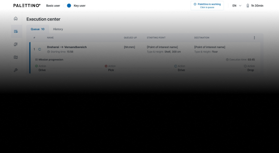
One of the client’s fundamental requirements was tracking a robot mission in real time, so we set the execution time to update every second.

A Key user can change the order of queued missions.

Mission removal is available for a Key user. They need to click the appropriate menu item and follow the additional action confirmation.

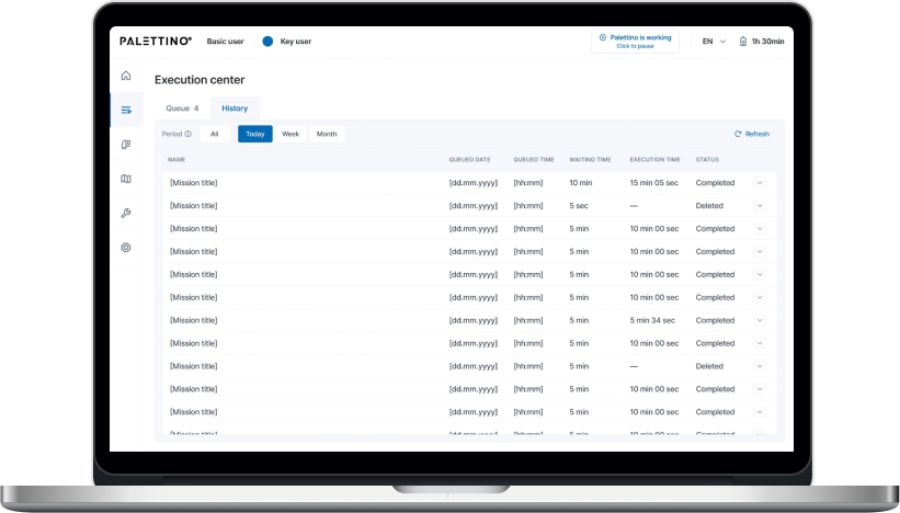
Only a Key user can access the History of missions and filter them by date:

  • Today
  • Week
  • Month

All missions are shown by default.

That’s what the clickable prototype looks like.

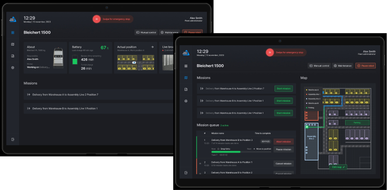
Dashboard for monitoring robot condition

The complex interface wasn’t the only reason the client’s customers considered previous forklift systems not user-friendly enough. They also strived to have simple visualizations of the robot’s status to detect and fix machine maintenance issues before they snowball.

A dashboard with widgets and actual information about the robot’s state empowered users to switch to the ‘danger foreseen is half avoided’ principle and, thus, decrease machinery maintenance costs.

  1. Writing a test emulator for the app

The client’s web app is an example of an embedded solution that strongly depends on the hardware. In such cases, software testing takes a special place in SDLC. There are two ways to perform it:

  • Running the app directly on the robot. However, this was a no-go option, as the client wanted to fine-tune the new model’s sensors before the trade show. Transporting the forklift back and forth between their headquarters in Osterburken and our development hub in Warsaw would totally mess up the project’s timeline.
  • Testing software on an emulator. The client didn’t have an emulated environment that imitates the robot’s behavior, so we offered our help and built it.

As we were working on the emulator ourselves, the increased project scope could have put the *instinctools team in a tight spot, given the strict deadline. However, we managed to deliver the robust version of the app on the dot. Moreover, our emulator served as a temporary substitute for the solution’s service for the robot coordination, making it possible for the client to showcase the trailblazing forklift model at the trade show.

  1. Shaping the post-MVP backlog

Satisfied with the MVP results, the client decided to proceed with our partnership at the post-MVP stage, during which our team will broaden the functionality related to these three areas:

  • User management
  • Mission improvements
  • Mission assignment

Before

  • Complicated app meant for employees with an engineering background
  • Lack of visualization
  • Partly manual control over a forklift robot on-site

After

  • Intuitive app sets new standards in user-friendliness of robotics management software
  • Easy-to-grasp dashboards
  • Fully remote control of the forklift robots

Business value

  • Trailblazing warehouse solution for the SMB segment
  • Highly user-friendly UI suitable for non-technical staff makes the software stand up from the crowd of solutions designed for tech-savvy employees
  • Simplified software support due to a homogeneous tech stack
  • Interface with no more than three clicks to reach any feature
  • Less than 0.4 sec response to the user input
  • Real-time updates of the robot missions
  • Easy-to-use dashboards for tracking a robot’s state
  • Decreased robot maintenance cost thanks to detecting malfunctions before they turn into serious issues

Client’s testimonial

Anna Vasilevskaya
AI modified real photo
Anna Vasilevskaya
Account Executive

Get in touch

Drop us a line about your project at
[email protected] or via the contact
form below, and we will contact you soon.